Structure
Framing, beams, posts, and footings
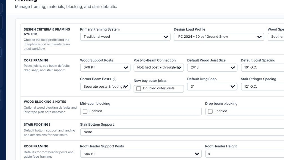
Choose Traditional wood, Owens Corning Lumber, New Castle Steel, or Fortress Evolution, then set member sizes, spacing, beams, posts, and footings.
Use this reference to
- Choose the correct primary framing system before sizing members
- Understand project defaults, bay exceptions, and member overrides
- Trace each structural choice into plans, details, 3D, and takeoff
Reference scope
- Primary control
- Current Job Settings > Framing Specs
- Override levels
- Bay, beam, post, footing
- Primary views
- Framing and Foundation Plan
- Final authority
- Controlling tables, manufacturer data, engineering
Choose the primary framing system first
Primary Framing System is not a label applied after the layout is complete. It changes the available members, span review, blocking, stairs, connection details, 3D geometry, and takeoff components.
System families remain separate; do not substitute one manufacturer’s members or details into another system.
| System | Joists and spacing | Beams and posts | System-specific output |
|---|---|---|---|
| Traditional wood | Selected species/profile; nominal 2x6, 2x8, 2x10, or 2x12 at 12, 16, or 24 inches O.C. where supported | Built-up lumber beam size and plies; 4x4, 4x6, 6x6, or 8x8 PT support posts | Wood blocking, joist tape, wood connection details, lumber cut planning, and wood takeoff |
| Owens Corning Lumber | Supported OC composite structural assemblies and manufacturer-table spacing | Two- or three-ply OC beams with OC 4x4 or 6x6 structural posts | OC stock lengths, blocking, stairs, colors, TER-based checks, connection schematics, and takeoff |
| New Castle Steel | NCS joist assembly/gauge at supported 12- or 16-inch spacing | Single or double NCS box beam with the NCS system post | Track/rim members, selected feature-board support, manufacturer tables, NCS details, 3D, and takeoff |
| Fortress Evolution | Evolution 2x6 16-ga joists at supported spacing | Single or double Evolution 2x11 beam with the 3.5-inch system post | S-Ledger/U-Rim members, blocking, straps, brackets, Fortress details, 3D, and takeoff |
Start with job-wide defaults
Current Job Settings defines the framing system, joist assembly and spacing, normal beam, support post, footing method, structural criteria, and related project assumptions.
The compact Beam and Joist chips above the Framing canvas show the effective project choices and open comparison tools. Keep project values representative of most of the job; use lower-level controls only where the built condition differs.
| Control level | Use it for | Do not use it for |
|---|---|---|
| Project | The normal framing system, joist assembly/spacing, beam assembly, post, loads, and footing method | One unusual bay or a single obstructed support |
| Selected bay | A section that truly needs different joist direction, attachment, beam layout, or supported section-level exception | Changing one beam in an otherwise normal bay |
| Beam Settings | One beam’s assembly, mount, post count/spacing, post size, footing size, or end condition | Rewriting the project default for every future beam |
| Footing menu | One support’s inherited/forced size, visibility, deep-footing state, or supported foundation-specific override | Opening a separate right-side footing inspector—the right inspector remains bay-level |
Set member sizes, spacing, and support type
In Current Job Settings > Framing Specs, choose the primary system before selecting its available joist, beam, post, and support options. Traditional wood exposes nominal lumber choices; Owens Corning, New Castle, and Fortress replace them with their supported system assemblies.
For traditional wood beam posts, Plan Advisors checks modeled height from footing or pier top to the beam underside against the selected IRC R507.4 load, species, and tributary-area row. It can recommend 8x8 when a smaller post does not fit below 14 feet. Every listed size, including 8x8, stops at 14 feet, so a taller post requires project-specific post, bracing, connection, and foundation design or a revised support layout.
Footing Type is independent from the primary framing system. The available project choices are Concrete, Helical, American Ground Screw, and Diamond Pier. Concrete projects also retain the applicable footing sizing and shape controls.
Choose the beam arrangement before fine support placement
- Front Only: common attached deck with one front support line.
- Front + Mid: adds an intermediate support line.
- Front + Rear: common freestanding arrangement.
- Auto Span: lets DeckDraft add support based on the implemented span rules.
- Opposite Ledger choices: move structural attachment and framing direction to another edge.
Override the exception—not the entire job
Use selected-section joist and support controls when one part of the deck truly differs. Use Beam Settings when a particular beam needs a different assembly, mount, post count, spacing, overhang, post size, or footing size.
Manual post locations are preserved intentionally. Review them after changing beam size, framing system, or support criteria.
| Change | Plan effect | Other affected output |
|---|---|---|
| Joist size or spacing | Joist linework, labels, spans, cantilever review, and blocking relationships update | 3D members, takeoff lengths/counts, details, advisors, and plan callouts |
| Beam assembly or mount | Beam depth/type, support spans, joist bearing or hanger condition, and labels update | Posts/footings, 3D, connection details, hardware allowances, and takeoff |
| Post count or manual post location | Support centers, dimensions, tributary areas, and footing markers update | Foundation Plan, beam review, 3D supports, concrete/pier schedule, and takeoff |
| Footing type or size | Foundation symbols, labels, and review status update | Concrete or pier quantities, applicable detail, schedule, and exported Foundation Plan |
Read checks as review information
DeckDraft compares modeled spans, cantilevers, and support conditions against its implemented project or manufacturer profiles. A passing result is not project engineering, and a review marker does not automatically mean the design is impossible.
Professional framing review
- Confirm the selected primary system matches the intended supplier and details
- Verify design loads and the controlling span/table profile
- Review every joist span, cantilever, beam support span, and end cantilever
- Confirm dropped versus flush beam connections and required blocking or hangers
- Check manual posts, shared beam runs, footing locations, and field obstructions
- Coordinate ledger, lateral-load, corrosion, connector, and fastener requirements
- Review Framing, Foundation Plan, Details, 3D, Takeoff, and exported callouts together
- Escalate conditions outside implemented tables or manufacturer scope
Still unclear?
Ask Docs AI about this page, or open DeckDraft when you need AI Help to read the active job.