From the first framing decision to the plans you hand over. Explore the control behind your design, the checks that guide it, and the ways you can present it.
Your construction methods. Room to make them work.
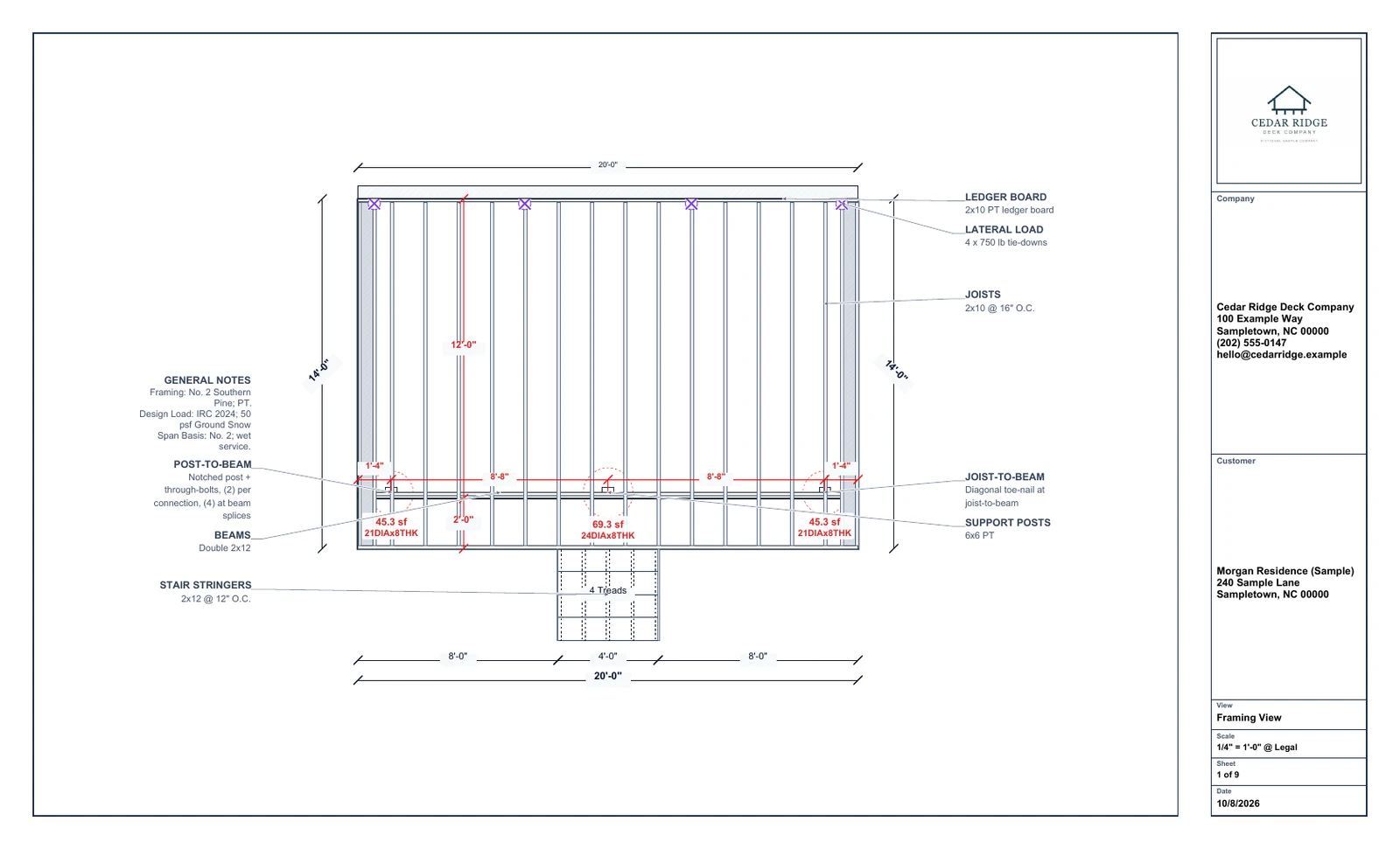
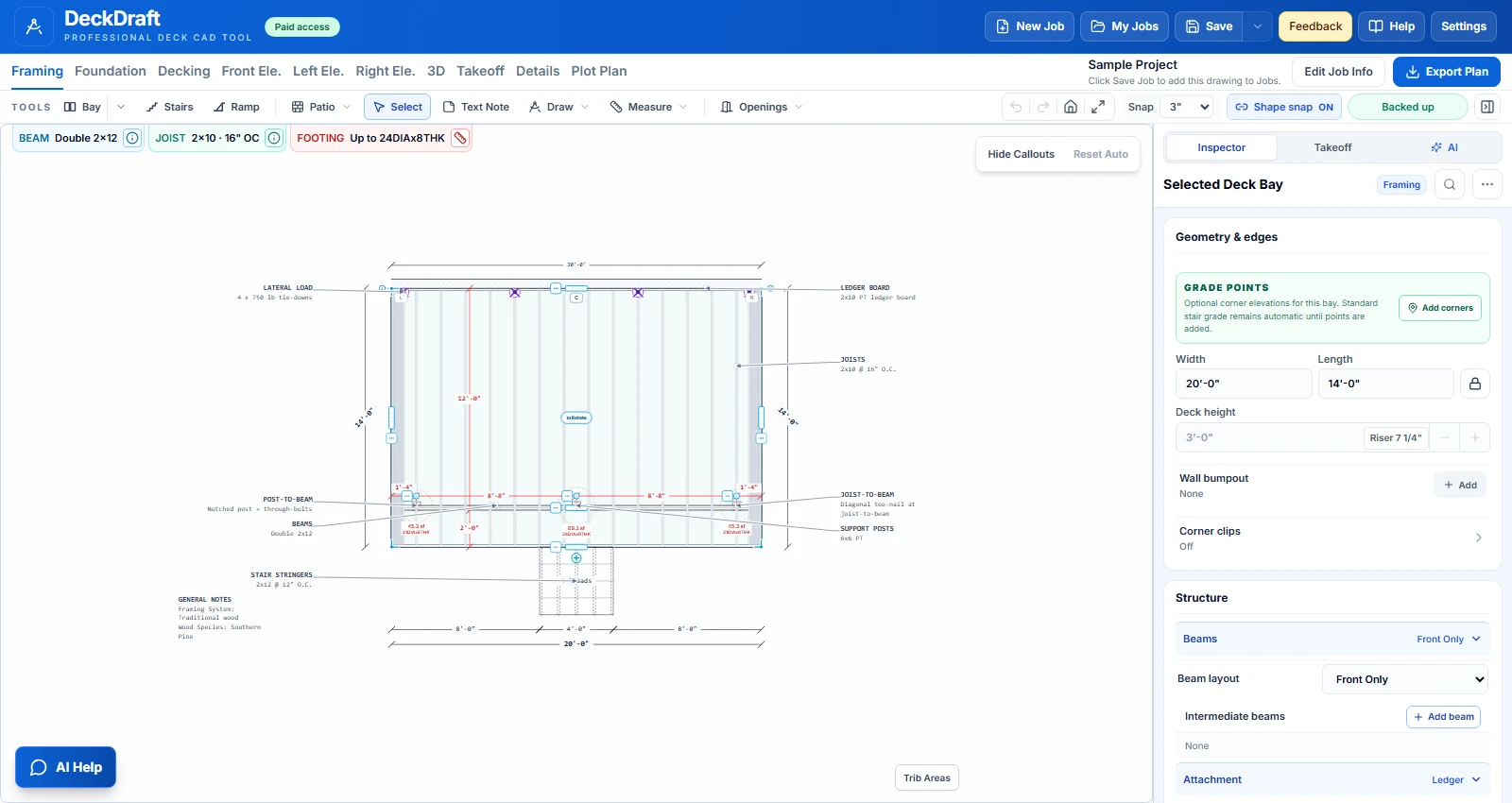
Adapt the deck to the job with control over geometry, materials, member sizes, support placement, connections, and foundations. Built-in span checks help you see where a change needs attention.
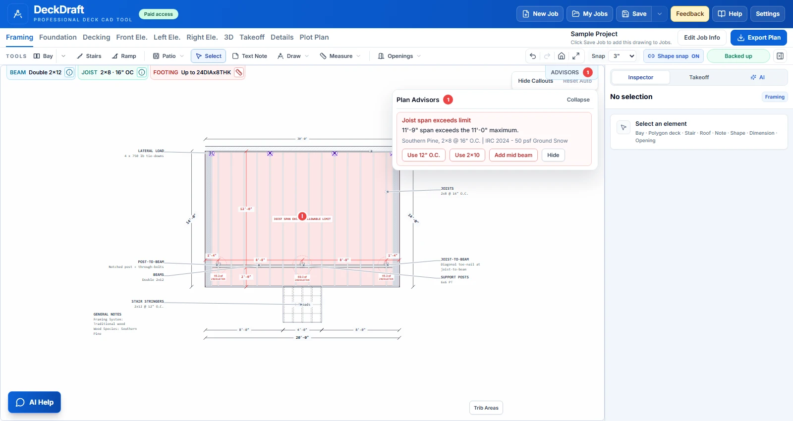
Shape the layout and configure the framing↗Review spans and correction options as you adjust↗
Fit the site
Combine bays, adjust dimensions, add clipped corners and bump-outs, and work with stairs, landings, and house context.
Down to how you block it
Ladder blocking or flat 2×4 / 2×6 support between joists for picture-frame and feature boards. Drop or upset beams. Notched, bolted, or post-cap connections. These are construction choices you control, with your usual methods saved as installer defaults.
Keep the guardrails
Compare actual and allowable spans, review footing capacity, and see conditions needing correction under your selected design profile.
Layout & geometry+
Deck shape
Connected rectangular deck bays
Magnetic edge snapping and bay locking
Exact feet-and-inches width and depth entry
Resize, move, connect, and disconnect sections
Clipped front corners
Grill bump-out preset
Automatic drawing work
Automatic overall and bay dimensions
Live dimensions while geometry changes
Framing-direction rotation by bay
Ledger and exterior-edge orientation
Text notes, rectangles, lines, circles, and polygons
House & access conditions
House walls, bump-outs, and returns
Windows, doors, and sliders
Stairs and stair landings
Connected deck landings
Ramps and access geometry
Wood & steel framing+
Traditional wood
Southern Pine joist tables
Douglas Fir-Larch, Hem-Fir, and Spruce-Pine-Fir tables
2x6, 2x8, 2x10, and 2x12 joists
12, 16, and 24 inches on center
Double and triple built-up beams
Advanced, engineered, glulam, and custom beam choices where supported
4x4, 4x6, 6x6, and 8x8 support posts
New Castle Steel
1 5/8-inch, 18-gauge joists
2-inch, 14-gauge joists
Single, every-other doubled, and all-doubled assemblies
NCS box beams in single and double configurations
NCS 6x6 steel support posts
12- and 16-inch joist spacing
Manufacturer tables for 50, 75, and 100 psf loads
Fortress Evolution
Evolution 2x6 joists in 16- and 18-gauge
Evolution 2x11 single and double beams
Evolution 3.5 x 3.5 steel support posts
Manufacturer tables for 50, 70, 75, and 100 psf loads
System-aware steel framing and stair controls
Support conditions
Feature-board and picture-frame support: ladder blocking, joist + flat 2x4 + joist, or joist + flat 2x6 + joist
Feature-board blocking method saved in installer defaults
Drop and upset beams
Front, rear, and intermediate beams
Automatic beam-span placement
Joist and beam cantilevers and overhangs
Notched, bolted, and Simpson post-cap connections
Tension ties, lateral bracing, and under-deck bracing
Existing-framing conditions
Span tables & plan advisors+
Built-in span profiles
IRC 2021: 40 psf live load
IRC 2021: 50 psf ground snow
IRC 2021: 60 psf ground snow
IRC 2021: 70 psf ground snow
IRC 2024: 40 psf live load
IRC 2024: 50 psf ground snow
IRC 2024: 60 psf ground snow
IRC 2024: 70 psf ground snow
AWC DCA 6: 2018 IRC format, 40 psf live load
AWC DCA 6: 2015 IRC, 40 psf live load
AWC DCA 6: 2012 IRC, 40 psf live load
Compliance Advisor
Joist-span checks
Joist-cantilever checks
Beam-span checks
Beam-overhang checks
Footing-capacity checks
Actual and allowable values shown together
Resolving actions tied to the affected component
Design Advisor
Optional member-sizing ideas
Support-layout suggestions
Spacing alternatives
Material-use opportunities
Clearly separated from conditions requiring attention
Foundations & calculations+
Concrete footings
Uniform-minimum, per-beam, and per-footing sizing modes
1,500, 2,000, and 3,000+ psf soil-bearing inputs
Main and ancillary footing defaults
Tributary-area calculations and labels
Per-footing size and depth overrides
House-adjacent deep-footing review
Helical piles
Pile model and minimum installation depth
Helix and shaft diameter
Rated pile capacity
Simple-detail or load-schedule reporting
Dead-load, torque Kt, and safety-factor inputs
Required and installation torque by pier
Capacity and utilization reporting
Other foundation systems
American Ground Screw models and flange inserts
Ground-screw diameter, soil class, and capacity
Frost-depth and maximum-installation-torque checks
Diamond Pier support selection
Foundation-plan symbols, schedules, and details
Foundation calculations and reports are planning aids. Verify the selected system, site conditions, manufacturer requirements, and engineering needs for the project.
Company & project setup+
Project setup
Customer, address, jurisdiction, and project information
Design-load and span-profile selection
Company framing and footing defaults
Installer construction and product defaults
Saved job reopening and revision workflow
Company workflow
Company branding on plan output
Shared company jobs
Additional team-user access
In-workspace AI Help for supported tools and workflows
Context from the current view and selected item for workflow guidance
Supported drawing edits through chat, with normal Undo
Organization platform for lumberyards and drafting teams in development
Checks support your judgment. Site conditions, local requirements, and projects needing engineering still require the appropriate review.
02 / Decking & railing
Work through the details your customer will see.
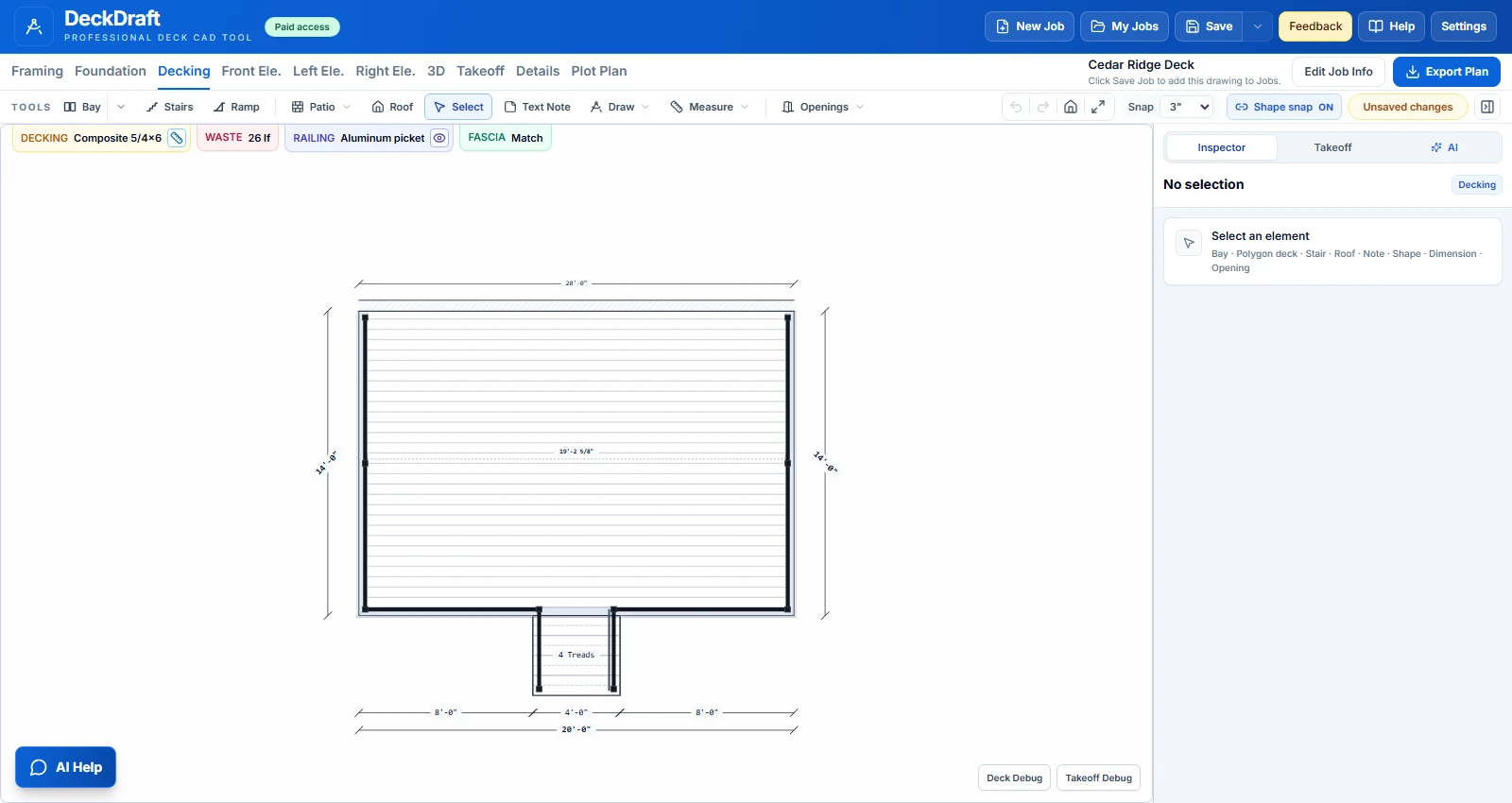
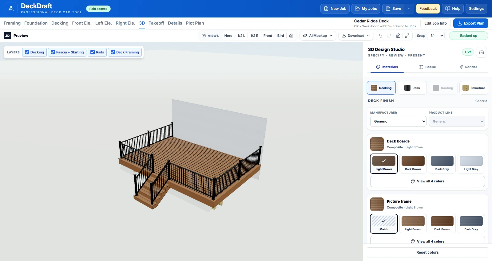
Develop the finished deck on the same model. Explore board layouts, borders, railing styles, and material choices alongside the structure beneath them.
Plan the field, borders, and finish materials↗Review the finished design in 3D↗
Board-by-board decisions
Set direction by region, straight or diagonal layouts, picture-frame borders, and seam boards. Assign materials separately to field boards, borders, fascia, and risers.
Railings that suit the design
Place rails by edge and explore picket, cable, or glass infill. Coordinate stairs, skirting, and finish choices with the rest of the deck.
See the whole project
Move between plan, elevations, and interactive 3D to review proportions and materials before presenting the design.
Decking, rails & views+
Decking layout
Field-board direction by region
Straight and diagonal layout controls
Picture-frame border boards
Seam and feature boards
12-, 16-, and 20-foot stock-length snapping
Board-span and over-20-foot review
Role-specific field, border, seam, fascia, and riser materials
Rails & finish
Rail placement by deck edge
Picket, vertical cable, horizontal cable, and glass infill
Fascia and riser finish controls
Skirting and enclosure choices
Manufacturer colors and material previews where available
Review views
Front, left, and right elevations
Interactive 3D review
House-wall and roof context
Framing, railing, and material controls in 3D
Customer-facing preview images
Optional AI concept mockups (beta)
03 / Covered decks & porches
Show them the space they’ll want to spend time in.
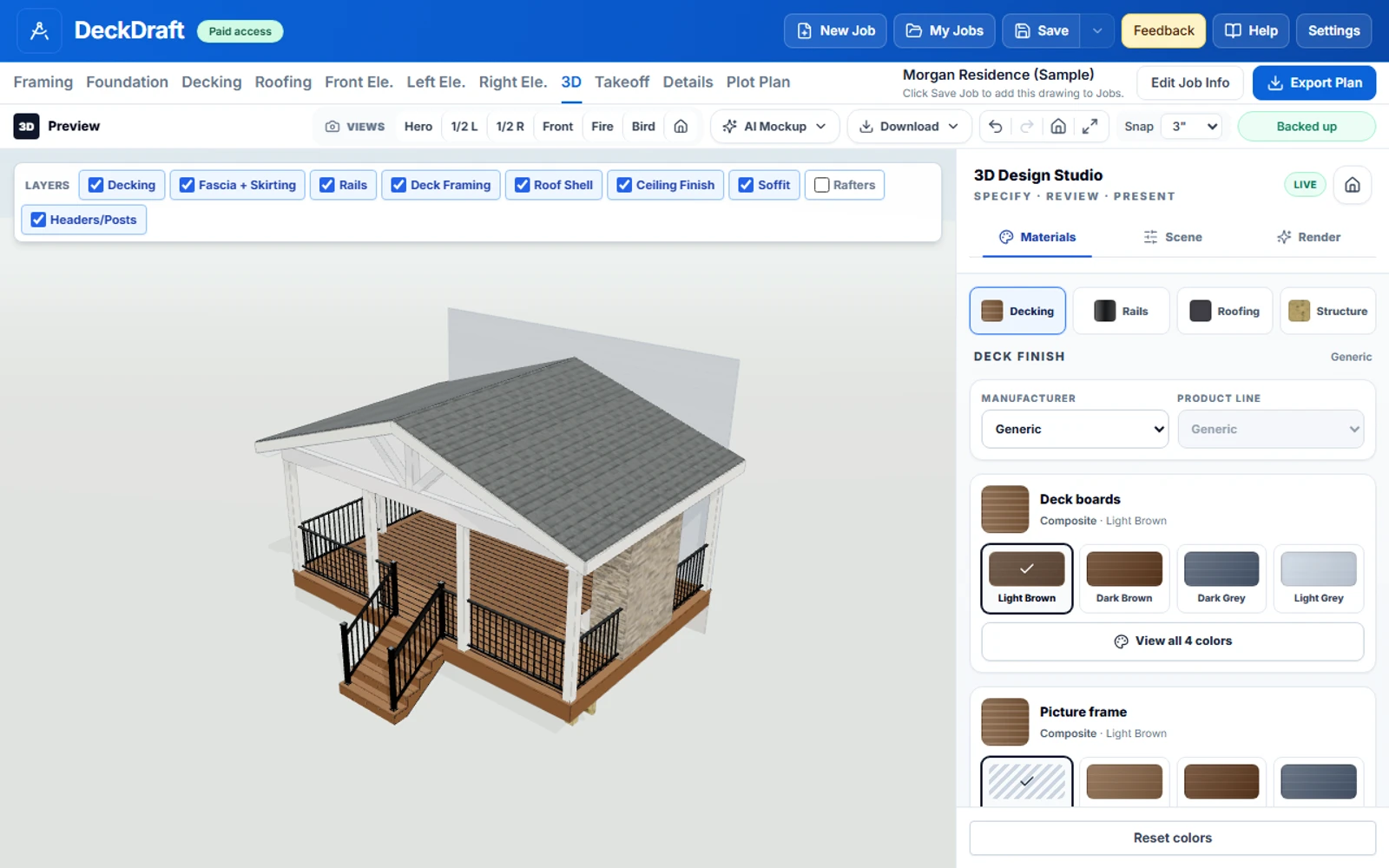
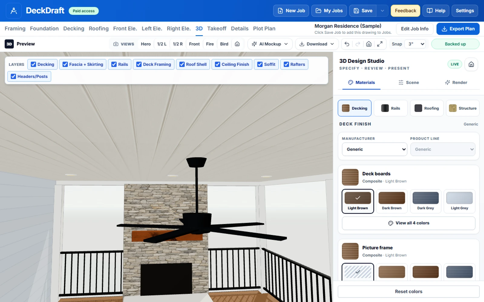
Bring the roof, ceiling, lighting, and fireplace into the conversation. Covered-deck tools help you develop the design and show the experience of the space in 3D.
Exterior: roof shape, gable details, and finishes↗Interior: ceiling, lighting, fan, and fireplace↗
Design the cover
Explore roof configurations, supporting posts, gable details, and finishes in the context of the deck and house.
Make it feel complete
Bring ceiling finishes, lighting, fans, and fireplace options into the model so customers can understand the space.
Keep expanding the idea
Covered-deck capabilities are actively expanding. The current tools support design and visualization; roof structural requirements need project-specific review.
04 / Presentation & output
One project. More ways to move it forward.
Help a customer picture it, prepare an HOA or permit submission, and review the materials. Carry the work from design into the documents and visuals the next conversation needs.
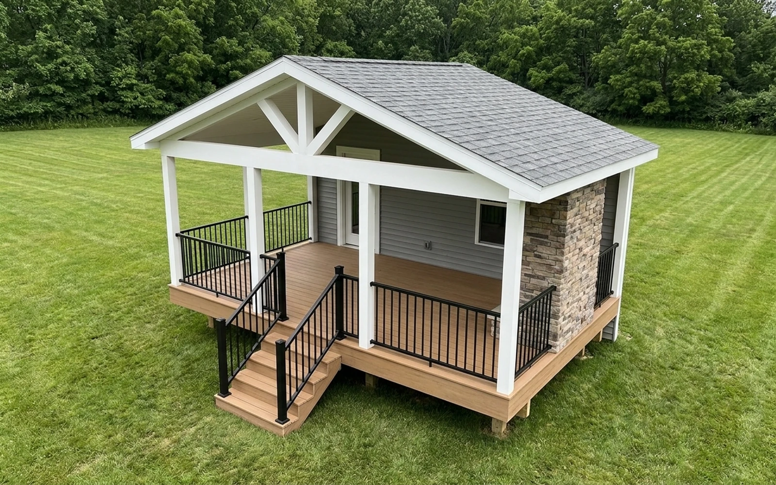
AI concept rendering of the covered-deck project above↗
From the model to the presentation
Start with the project’s 3D view, then use AI rendering to explore a more finished presentation for your customer.
AI rendering is a concept tool in beta. Generated details can vary from the model; use the drawings for dimensions and construction information.
Plot plans: show the deck in its site context↗Takeoffs: review quantities from the model (beta)↗
Permit & HOA packages
Combine framing, foundations, decking, elevations, details, and project notes into a branded PDF. Include your logo and company, customer, and project information.
Site context
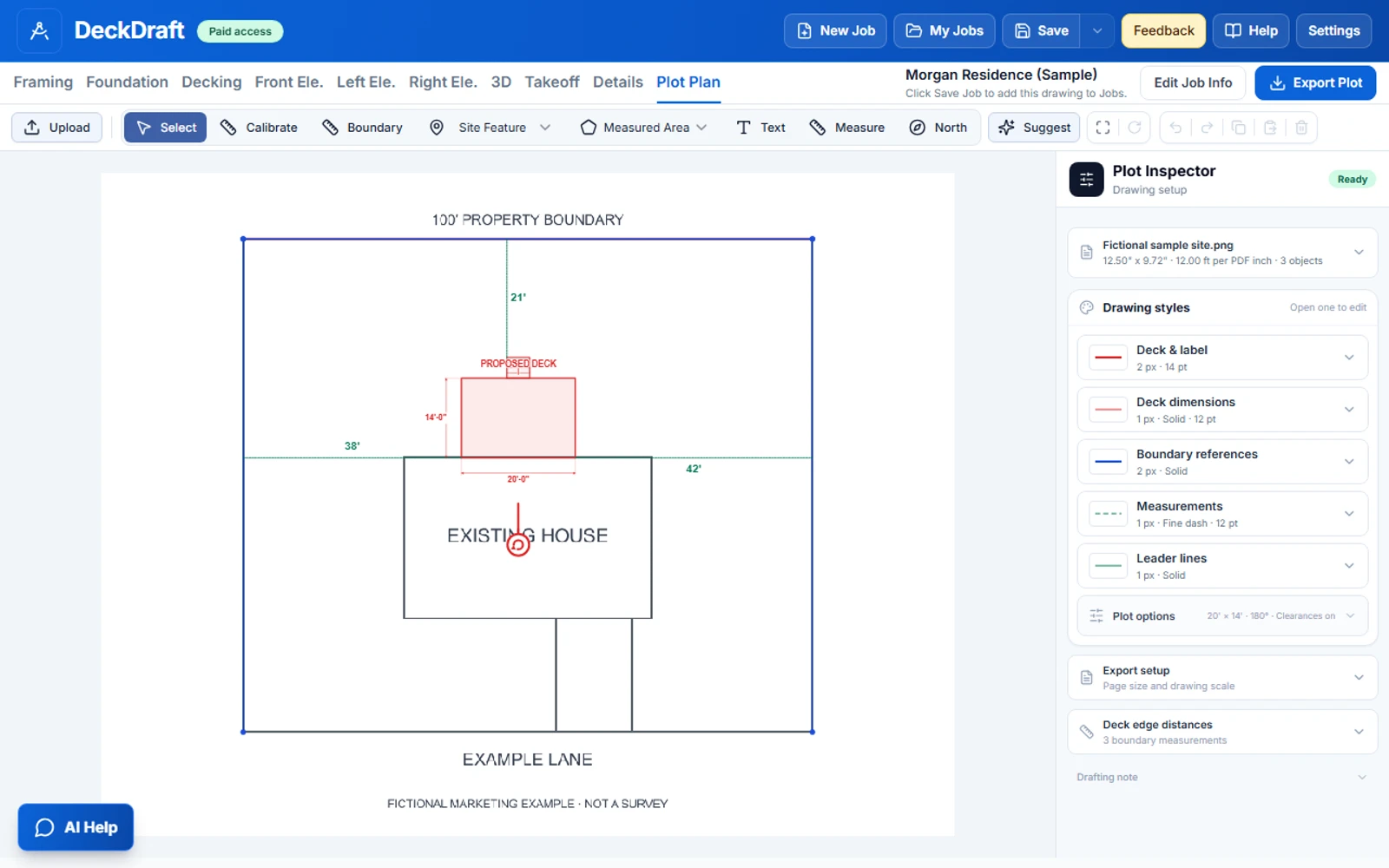
Show where the proposed deck sits using plot-plan context. The example uses a fictional property base; use appropriate site information for your project.
Material planning
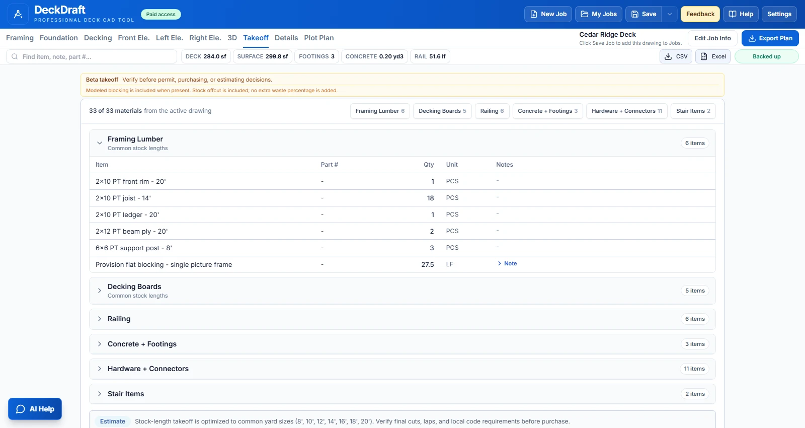
Review framing, decking, railing, and foundation quantities together. Confirm quantities and product selections before ordering.
Takeoff, details & output+
Material takeoff (beta)
Framing-lumber quantities and stock lengths
Decking-board quantities
Railing quantities
Concrete and footing quantities
Model-based category summaries
Review and part-number workflow before purchasing
Construction details
Footing and foundation details
Post-to-beam connections
Joist-to-beam connections
Ledger-to-house details
Lateral-load details
Rail-post details
System-aware wood or steel detail selection
Plan package
Framing and foundation views
Decking plan and elevations
Details and project notes
Plot-plan context
Drawing annotations
Company, customer, and project information
Branded multi-sheet PDF export
05 / AI Help & support
Help that stays with your drawing.
Ask in plain language while you work. The assistant uses the current view and selected item to explain supported workflows, point you to the right controls, and make supported drawing changes. Direct support is here when you need a person.
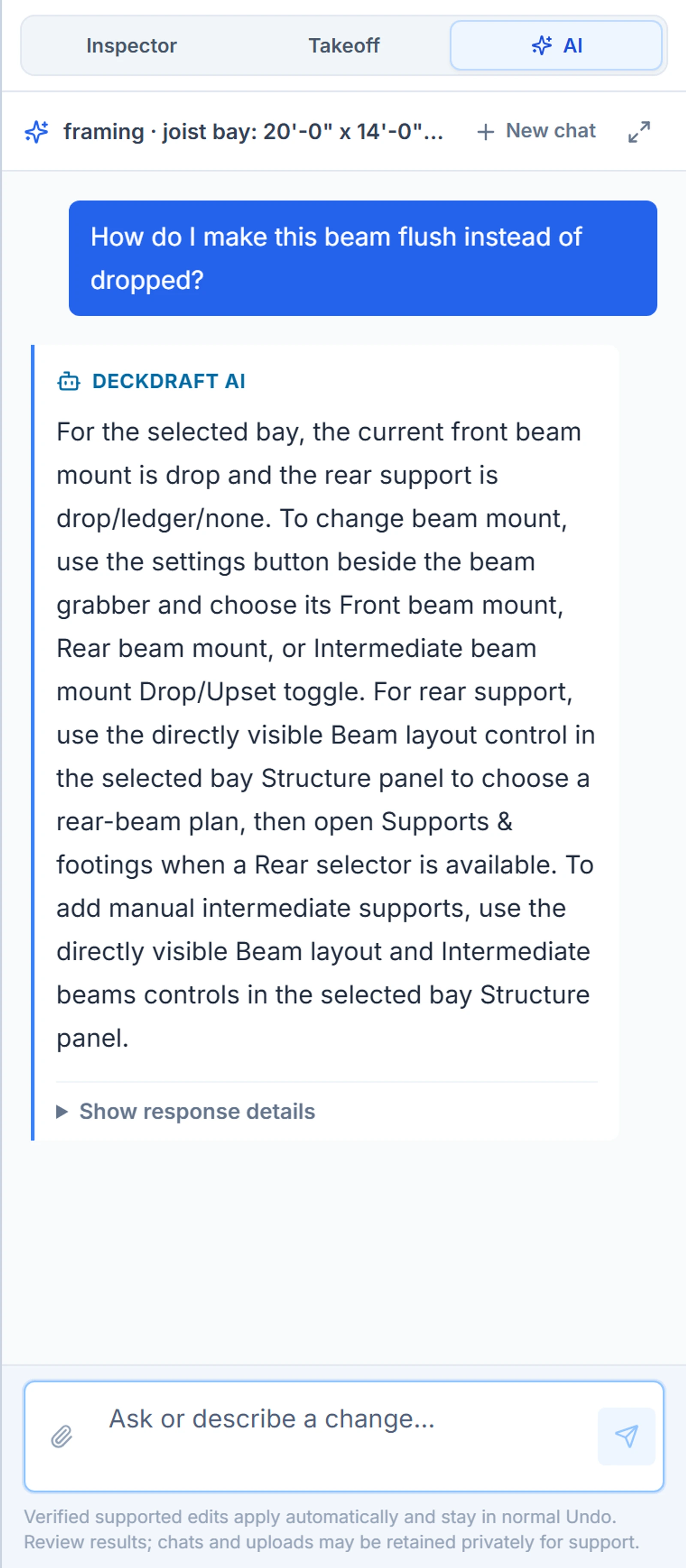
An answer about the bay you selected.
Ask about a flush beam and the assistant identifies the current beam mount, then points you to the controls for changing it.
Actual AI Help conversations on a fictional sample project. Review answers and drawing changes against your project requirements.